Why Panduit Cable Cleats Are The Best Choice?
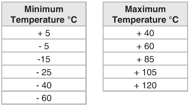
- Temperature rating (-60˚C to +120˚C)
- Resistance to flame propagation (very similar to UL 94)
- Lateral load testing (at maximum declared temp)
- Axial load testing (at maximum declared temp)
- Impact resistance (at lowest declared temp)
- Corrosion and UV resistance
- Resistance to electromechanical forces
- The test report shall contain the following information: The manufacturer’s or responsible vendor’s catalog references of the cable cleat and intermediate restraint (where used);
- Assembly details showing:
- Number of cleats and their spacing
- Number of intermediate restraints (where used) and their spacing
- The cable center spacing
- Cable conductor diameter, insulation thickness, external diameter and markings
- Pre-test photograph of the test assembly and a post-test photograph documenting the condition of the cable cleats, and intermediate restraints if used
- The test duration
- The ambient temperature during the test
- For cable cleats and intermediate restraints classified for one short circuit: Cleats and intermediate restraints shall comply with the following requirements: No failure that will affect the intended function of holding the cables in place
- The cable cleats and the intermediate restraints, if used, shall be intact with no missing parts including all devices used to secure the cleats to the mounting surface
- No cuts or damage visible to normal or corrected vision to the outer sheath of each cable caused by the cable cleats or by the intermediate restraints, if used.

Panduit cable cleats ensure cables remain contained in the event of a short circuit fault, minimising disruption and damage to personnel and property. Uniquely engineered for ease of installation in a range of applications and harsh environments, Panduit has the right product to fit your needs while providing on the job productivity, reliability and safety.

Why choose Panduit?

Panduit’s cable cleat solution is the industry’s first solution that has streamlined the selection process, tested to IEC standards bringing the vision of creating an engineering specifiable products to the EPC and Contractor firms. Panduit’s cable cleats have simple and intuitive design that helps to improve productivity, have industry-unique mounting brackets and installation tools, and are compatible with a variety of ladder racks and cables.
Test Methodology
The rest of this article will explore IEC 61914:2015 standard at a high level outlining the methodology and testing criteria to successfully design and test a Panduit’s cable cleat to meet standard requirements as well as the appropriate methodology to correctly specify a cleat system in the protection against a short circuit fault.
The standard provides harmonized testing procedures and declarations for the
following aspects:
- Temperature rating (-60˚C to +120˚C)
- Resistance to flame propagation (very similar to UL 94)
- Lateral load testing (at maximum declared temp)
- Axial load testing (at maximum declared temp)
- Impact resistance (at lowest declared temp)
- Corrosion and UV resistance
- Resistance to electromechanical forces
Temperature Rating
Lateral load testing
A cable cleat intended for a single mounting orientation is tested in that orientation and that
orientation shall be declared in the documentation. A cable cleat intended for multiple mounting orientations is tested in each mounting orientation using separate samples.

Figure 2: Testing of cleat lateral load
Axial Load Testing
The test should be carried out at the maximum declared temperature using a mandrel with an overall cross section equivalent to the minimum declared cable cross section for which the cleat is designed. The test mandrel shall have a diametrical tolerance of (+0.2/-0.2) mm for mandrels up to and including 16 mm diameter and of (+0.3/-0.3) mm for larger diameters.
After the test, the displacement of the mandrel(s) with respect to the cleat shall not
be more than 5 mm.
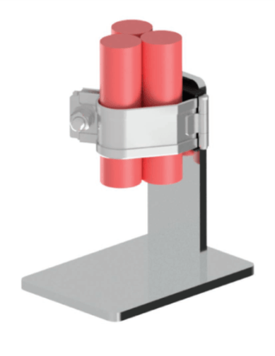
Fig. 3: Testing of cleat axial load
Impact Resistance
Highest Declared Temperature
Before the test, the samples are assembled onto a solid polyamide or metal test mandrel having a diameter equivalent to the maximum declared diameter for which the cleat is designed and mounted on a rigid support.
The impact is applied within a period of (10 +0/-2) s after removal from the refrigerator. Each sample is placed in position on the steel base as shown in Fig. 10. The energy value of the hammer is as declared in table.
The impact is applied at the weakest point of the cleat or intermediate restraint and the direction of impact is radial to the center of the mandrel nearest to the point of impact. After the test, the samples shall show no signs of disintegration nor shall there be any cracks or damage, visible to normal or corrected vision, that are likely to impair normal use.

Fig 4: Testing of impact resistance
Corrosion Resistance
Metallic or composite cleats and intermediate restraints shall have adequate resistance to corrosion. Compliance is determined by conducting a salt spray test unless otherwise specified.
Salt Spray Test
All grease shall be removed from the parts prior to testing by cleaning with white spirit. All parts shall then be dried and samples assembled on a nylon mandrel with a diameter equal to the smallest cable diameter declared for the cleat or intermediate restraint. Samples shall be subjected to a neutral salt spray test according to ISO 9227. After the parts have been dried for a minimum of 10 min while heated in a cabinet reaching 100 (+/- 5) °C. Any traces of rust on sharp edges and a yellowish film may be removed by rubbing. The sample shall have passed the test if there is no red rust visible to normal or corrected vision. Zones that trap saltwater during the test are not considered for the test result.
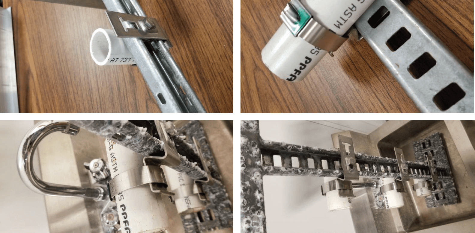
Fig 5: Salt spray test
UV Resistance
When the product is provided in more than one color, the color having the heaviest organic pigment loading shall be subjected to this test. The samples tested are considered representative of the entire color range. Samples shall be mounted in the ultraviolet light apparatus in a convenient manner suitable for the product to be tested. Samples should not touch each other. The samples are to be exposed for a minimum of 700 h to Xenon-arc, Method A, Cycle 1 in accordance with ISO 4892-2:2006. There shall be continuous exposure to light and intermittent exposure to water spray.
The cycle consists of 102 min without water spray and 18 min with water spray. The apparatus operates with a water-cooled xenon-arc lamp, borosilicate glass inner and outer optical filters, a spectral irradiance of 0.51 W/(m2•nm) at 340 nm and a black-standard temperature of 63°C. The temperature of the chamber is 38.3°C. The relative humidity in the chamber shall
be 50%. Following the exposure, the samples are held for a minimum of 30 min under ambient conditions. After UV exposure, the samples showing no signs of disintegration nor any cracks or damage, visible to normal or corrected. The samples will then be subjected to the impact test, described above and shall comply with the impact test requirements.
Resistance to Electromechanical Forces]
A short-circuit test is carried out as follows, using the manufacturer’s or responsible vendor’s declared values of peak short-circuit current (ip) and initial r.m.s. symmetrical short-circuit current. One set of cleats of each type and of a size suitable for the test cable shall be tested.
The test is performed using unarmored single core 600 V / 1000 V stranded copper conductor cable of either (35 +5/-5) or (50 +5/-5) mm diameter.
The test is carried out at the prevailing ambient temperature on the declared arrangement at the declared short-circuit level. The ambient temperature shall be recorded in the test report.
The arrangement of the cables can be true touching trefoil or flat, spaced formation with one cable per phase. One end of the cable is connected to a three-phase supply and the other end to a short-circuiting busbar with all three phases being connected. The short-circuiting busbar shall be insulated from earth.
The cable is restrained at a minimum of 5 positions along the cable run. Where intermediate restraints are used, at least 4 cleats and at least 3 intermediate restraints shall be used. Cleats and intermediate restraints, where used, shall be equally spaced. The cleats are fixed to a mounting surface defined by the manufacturer (e.g. cable ladder) which shall be selected regarding the forces likely to occur during the test.
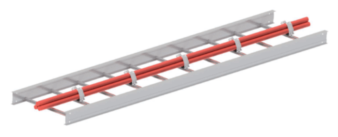
Fig 6: Testing for Resistance to Electromechanical Forces
Care is taken to ensure the cross-sectional area of the cable is adequate for the magnitude and duration of the test current which shall be chosen so that the thermal stress rating of the cable used is not exceeded.
- The test report shall contain the following information:
- The manufacturer’s or responsible vendor’s catalog references of the cable cleat and intermediate restraint
(where used); - Assembly details showing:Number of cleats and their spacing
- Number of intermediate restraints (where used) and their spacing
- The cable center spacing
- Cable conductor diameter, insulation thickness, external diameter and markings
- Pre-test photograph of the test assembly and a post-test photograph documenting the condition of the cable cleats, and intermediate restraints if used
- The test duration
- The ambient temperature during the test
If the test station must undertake a calibration test, action is taken to ensure that the test installation is not affected. The cables of the test arrangement are subjected to a three-phase short circuit of duration of not less than 0,1 s. The duration of the test is recorded. Care must be taken to ensure that there is adequate restraint for the cables at each end of the cable run to be tested.
- For cable cleats and intermediate restraints classified for one short circuit:
Cleats and intermediate restraints shall comply with the following requirements:
No failure that will affect the intended function of holding the cables in place - The cable cleats and the intermediate restraints, if used, shall be intact with no missing parts including all devices used to secure the cleats to the mounting surface
- No cuts or damage visible to normal or corrected vision to the outer sheath of each cable caused by the cable cleats or by the intermediate restraints, if used.
For cable cleats and intermediate restraints classified for two short circuits:
Cleats and intermediate restraints shall comply with the inspection after the first and after the second short-circuit applications. After a second short-circuit application, a voltage withstand test is performed by applying a minimum test voltage of 2,8 kV d.c. or 1,0 kV a.c. for a period of (60 +5/0) seconds according to the provisions of IEC 60060-1:2010, Clause 5.
The voltage withstand test is administered between the cable cores, which should be connected including the mounting frame. The mounting frame shall be bonded to the earthing system. The cable jackets and mounting frame be pre-wetted with enough water to facilitate a current leakage path along the outer jacket for (2 +1/0) mins before the test begins. The cables meet the requirements of the voltage withstand test without failure of the insulation.

Share this article on social media