Strapping Bands vs Cable Cleats - Exposing the Misconception
Definition of Cable Cleat
[/split_line_heading][vc_column_text]Defined by the IEC International standard, a cable cleat is simply:“A device designed to secure cables when installed at intervals along the length of the cables”However, even though the standard does require the manufacturer to describe a material type, it does not exclude any specific material, dictate any minimum dimensions or physical attributes. Annex A (informative) in the IEC cable cleat standard provides examples of various cable cleats which include products made from timber, steel and plastic. There is a variety of designs and methods of ‘securing cables’, designs start at 15mm wide and go up to 150mm wide. Cable cleats are required to follow IEC 61914:2015 standard, which is a high level outlining the methodology and testing criteria to successfully design.[/vc_column_text][image_with_animation image_url="8533" alignment="" animation="Fade In" border_radius="none" box_shadow="none" max_width="100%"][divider line_type="No Line"][vc_column_text]Figure 1: Examples of Cable Cleats[/vc_column_text][divider line_type="No Line"][vc_column_text]Providing that the manufacturer tests and declares certain performance criteria, a ‘cable cleat’ can be any shape, size or material. Hence, for example, a 19mm wide banding system can be used to secure cables in line with the IEC Cable Cleat standard providing it undergoes all the required tests and that they are carried out in accordance with the standard. The term ‘cable tie’ is commonly used to describe a ‘strap cleat’ system which is not correct. A light duty stainless steel tie or an injection molded ‘zip’ tie has many uses and play a vital role on many cable routing installations, but they must not be confused with a high-end strap cleat solution which can withstand immensely high electro-mechanical forces and are resistant to corrosion and ultra violet degradation.[/vc_column_text][/vc_column][/vc_row][vc_row type="in_container" full_screen_row_position="middle" scene_position="center" text_color="dark" text_align="left" overlay_strength="0.3" shape_divider_position="bottom"][vc_column column_padding="no-extra-padding" column_padding_position="all" background_color_opacity="1" background_hover_color_opacity="1" column_shadow="none" column_border_radius="none" width="1/1" tablet_text_alignment="default" phone_text_alignment="default" column_border_width="none" column_border_style="solid"][split_line_heading]
The Misconceptions About Strapping Bands
[/split_line_heading][/vc_column][/vc_row][vc_row type="in_container" full_screen_row_position="middle" scene_position="center" text_color="dark" text_align="left" overlay_strength="0.3" shape_divider_position="bottom"][vc_column column_padding="no-extra-padding" column_padding_position="all" background_color_opacity="1" background_hover_color_opacity="1" column_shadow="none" column_border_radius="none" width="1/1" tablet_text_alignment="default" phone_text_alignment="default" column_border_width="none" column_border_style="solid"][split_line_heading]Misconception 1: A banding system cannot restrain the forces during a fault
[/split_line_heading][vc_column_text]Recent articles in the industry press suggest that a banding system is not capable of withstanding the electromechanical forces and a series of video clips show an incorrectly specified cable tie installation failing during fault. The issue here is that the tested product was not suitable for the intended installation. It might well have been the case that this weaker tie was specified by the system designer, and here lies the true problem, an incorrect specification. The product used in the test was never designed to withstand these forces; a correctly specified and engineered banding system certainly would.[/vc_column_text][divider line_type="No Line"][image_with_animation image_url="8541" alignment="" animation="Fade In" border_radius="none" box_shadow="none" max_width="100%"][vc_column_text]Figure 2: Example of an aftermath of an intentional short circuit fault during testing[/vc_column_text][divider line_type="No Line"][vc_column_text]To suggest that a strap banding system is not suitable for short circuit rated installations is incorrect and is out dated information. The cable system designer must make sure that the fault levels have been accurately calculated and then specify a fixing system which meets that requirement and complies fully to IEC 61914:2015.[/vc_column_text][/vc_column][/vc_row][vc_row type="in_container" full_screen_row_position="middle" scene_position="center" text_color="dark" text_align="left" overlay_strength="0.3" shape_divider_position="bottom"][vc_column column_padding="no-extra-padding" column_padding_position="all" background_color_opacity="1" background_hover_color_opacity="1" column_shadow="none" column_border_radius="none" width="1/1" tablet_text_alignment="default" phone_text_alignment="default" column_border_width="none" column_border_style="solid"][split_line_heading]Misconception 2: A banding system has sharp edges and will cut the installer during installation / damage the cable during fault conditions
[/split_line_heading][vc_column_text]As described previously, to achieve a successful short circuit test is difficult. After both the first and second short circuits each cable at every restraint position is inspected by test laboratory personnel; there can be no cuts or damage to the outer jacket. Furthermore, after the second short circuit the laboratory carry out the voltage withstand test to check for current leakage and any hidden damage which may have occurred underneath the band itself. Panduit’s extensive range of banding products have full certification to both classifications of short circuit test. The use of a protective sleeve moulding, common on many cleat types, and the use of rolled edge banding material ensures the cable is protected regardless of fault level. To suggest that this type of product is not suitable for short circuit rated installations because it will damage or cut the cable or cause cuts and injury to personnel is incorrect and out dated information.[/vc_column_text][divider line_type="No Line"][image_with_animation image_url="8537" alignment="" animation="Fade In" border_radius="none" box_shadow="none" max_width="100%"][vc_column_text]Figure 2: Panduit ANSYS simulation software showing electromagnetic forces during a short circuit event.[/vc_column_text][divider line_type="No Line"][vc_row_inner column_margin="default" text_align="left"][vc_column_inner column_padding="no-extra-padding" column_padding_position="all" background_color_opacity="1" background_hover_color_opacity="1" column_shadow="none" column_border_radius="none" width="1/1" column_border_width="none" column_border_style="solid"][vc_column_text]Other advantages of Panduit’s Banding Systems
[/vc_column_text][divider line_type="No Line"][vc_column_text]• When compared to a ‘traditional’ design of cable cleat the banding system has a much larger range taking ability. This is a huge advantage from a purchasing and stock keeping perspective; quite often one part number from a Banding System covers the same range take as perhaps four or five ‘traditional’ cleat part numbers. • A banding system takes up minimum space when installed around the cables. This is a very important factor when space is limited e.g. across the width of a ladder rung or when available height is limited e.g. between layers of ladder runs. • A fault rated band will be typically less expensive to buy and quicker to install. • A large quantity of banding system products takes up much less physical space on site before installation compared to ‘traditional’ cleat systems. This also leads to less packaging, less waste and generally a lower carbon footprint.[/vc_column_text][/vc_column_inner][/vc_row_inner][/vc_column][/vc_row][vc_row type="in_container" full_screen_row_position="middle" scene_position="center" text_color="dark" text_align="left" overlay_strength="0.3" shape_divider_position="bottom"][vc_column column_padding="no-extra-padding" column_padding_position="all" background_color_opacity="1" background_hover_color_opacity="1" column_shadow="none" column_border_radius="none" width="1/1" tablet_text_alignment="default" phone_text_alignment="default" column_border_width="none" column_border_style="solid"][nectar_btn size="small" button_style="regular" button_color_2="Accent-Color" icon_family="none" text="Download Whitepaper"][/vc_column][/vc_row][vc_row type="in_container" full_screen_row_position="middle" scene_position="center" text_color="dark" text_align="left" overlay_strength="0.3" shape_divider_position="bottom"][vc_column column_padding="no-extra-padding" column_padding_position="all" background_color_opacity="1" background_hover_color_opacity="1" column_shadow="none" column_border_radius="none" width="1/1" tablet_text_alignment="default" phone_text_alignment="default" column_border_width="none" column_border_style="solid"][gravityform id="7" title="false" description="false" ajax="false"][/vc_column][/vc_row]
Definition of Cable Cleat
Defined by the IEC International standard, a cable cleat is simply:
“A device designed to secure cables when installed at intervals along the length of the cables”
However, even though the standard does require the manufacturer to describe a material type, it does not exclude any specific material, dictate any minimum dimensions or physical attributes. Annex A (informative) in the IEC cable cleat standard provides examples of various cable cleats which include products made from timber, steel and plastic. There is a variety of designs and methods of ‘securing cables’, designs start at 15mm wide and go up to 150mm wide.
Cable cleats are required to follow IEC 61914:2015 standard, which is a high level outlining the methodology and testing criteria to successfully design.

Figure 1: Examples of Cable Cleats
Providing that the manufacturer tests and declares certain performance criteria, a ‘cable cleat’ can be any shape, size or material. Hence, for example, a 19mm wide banding system can be used to secure cables in line with the IEC Cable Cleat standard providing it undergoes all the required tests and that they are carried out in accordance with the standard.
The term ‘cable tie’ is commonly used to describe a ‘strap cleat’ system which is not correct. A light duty stainless steel tie or an injection molded ‘zip’ tie has many uses and play a vital role on many cable routing installations, but they must not be confused with a high-end strap cleat solution which can withstand immensely high electro-mechanical forces and are resistant to corrosion and ultra violet degradation.
The Misconceptions About Strapping Bands
Misconception 1: A banding system cannot restrain the forces during a fault
Recent articles in the industry press suggest that a banding system is not capable of withstanding the
electromechanical forces and a series of video clips show an incorrectly specified cable tie installation failing during fault. The issue here is that the tested product was not suitable for the intended installation. It might well have been the case that this weaker tie was specified by the system designer, and here lies the true problem, an incorrect specification. The product used in the test was never designed to withstand these forces; a correctly specified and engineered banding system certainly would.

Figure 2: Example of an aftermath of an intentional short circuit fault during testing
To suggest that a strap banding system is not suitable for short circuit rated installations is incorrect and is out dated information. The cable system designer must make sure that the fault levels have been accurately calculated and then specify a fixing system which meets that requirement and complies fully to IEC 61914:2015.
Misconception 2: A banding system has sharp edges and will cut the installer during installation / damage the cable during fault conditions
As described previously, to achieve a successful short circuit test is difficult. After both the first and second short circuits each cable at every restraint position is inspected by test laboratory personnel; there can be no cuts or damage to the outer jacket. Furthermore, after the second short circuit the laboratory carry out the voltage withstand test to check for current leakage and any hidden damage which may have occurred underneath the band itself. Panduit’s extensive range of banding products have full certification to both classifications of short circuit test. The use of a protective sleeve moulding, common on many cleat types, and the use of rolled edge banding material ensures the cable is protected regardless of fault level. To suggest that this type of product is not suitable for short circuit rated installations because it will damage or cut the cable or cause cuts and injury to personnel is incorrect and out dated information.
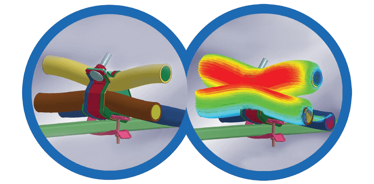
Figure 2: Panduit ANSYS simulation software showing electromagnetic forces during a short circuit event.
Other advantages of Panduit’s Banding Systems
• When compared to a ‘traditional’ design of cable cleat the banding system has a much larger range taking ability. This is a huge advantage from a purchasing and stock keeping perspective; quite often one part number from a Banding System covers the same range take as perhaps four or five ‘traditional’ cleat part numbers.
• A banding system takes up minimum space when installed around the cables. This is a very important factor when space is limited e.g. across the width of a ladder rung or when available height is limited e.g. between layers of ladder runs.
• A fault rated band will be typically less expensive to buy and quicker to install.
• A large quantity of banding system products takes up much less physical space on site before installation compared to ‘traditional’ cleat systems. This also leads to less packaging, less waste and generally a lower carbon footprint.

Share this article on social media