Relay | Electrical Characteristics of Relays
Electrical Characteristics of Relays
Electrical Characteristics of Relays - Different types of relays have different electrical characteristics and other characteristics. The common electrical characteristics of the general relays are as follows:
Rated Coil Voltage:
- The basic electrical characteristics of a relay are the rated coil voltage. The voltage at which the relay is made operational is called the rated coil voltage. The input voltage to the relay is also known as the rated coil voltage. The rated coil voltage is set up by the manufacturer and the different relays have different rated coil voltages. The coil of a relay is sensitive when the voltage exceeds the limit, and the coil of the voltage is damaged.
Set Voltage:
- The minimum voltage at which the switching operation is performed by the relay is known as the set voltage or operating voltage. The set voltage or the operating voltage of the relay is always less than the ideal coil voltage. The value for the set voltage is predefined by the manufacturer. Different relays have different set voltages.
Rated Power:
- The maximum power that a relay can handle is known as the rated power. For example, if a normal operating voltage of a relay is 60W then the rated power for the relay is less than 60W. The power consumption of the coil is called the power rating of the coil and it should not be more than the rated power. The power of the relays is expressed in milli-amperes and ampere ratings.
Switching Capacity:
- The maximum value of the current that the contacts of the relays can withstand is called the switching capacity. The switching capacity can also be defined as the capacity at which the switching operation is performed by the relay. The switching capacity is defined for the loads with a resistive nature which are connected with the contacts of the relays. Different relays have different switching capacities.
Problems and Status of Relay
There are numerous problems asserted with the relays. The different problems asserted with the relays are:
Capacitive Noise:
- The capacitive components used in the different relay loads cause the capacitive noise in relays. The capacitive noise can be removed in the relay with the help of the proper solution. Different manufacturers of the relays use different approaches to reduce the capacitive noise for better operation of the relays.
Long AC Signal Cables:
- The long cables of the AC signals cause a big problem in the relays which is interference in the relay. The different inferences in the relay due to the long cables lower the switching capability of the relays.
Solutions:
The diode circuit is used in the relays to overcome the issue of the leakage current and the directional flow in a relay.
Leakage Current:
- The other issue or problem asserted with the relays is the leakage current. The solution is using snubber circuits to prevent the leakage current in relays. The relays are manufactured to withstand the leakage current and the capacitive noise.
High-Frequency Suppression:
- The RC circuit is used in the relays for the solution of the high-frequency suppression and the transient in the relays. The interference in the relay is observed with the RC circuit used in the design of the relay.
Hysteresis and Switching Points:
- The switching point of the relay should be clearly separated. The different relays have different hysteresis and each relay has its own efficiency for the hysteresis. The electromechanical relays are the relays with the strong hysteresis and switching points while the other relays have lower hysteresis. The best switching points are observed in the relays. In the relays, the hysteresis circuit is used to find the switching point. The relays with the optocouplers have the weakest hysteresis.
Status Indication:
- An LED helps to indicate the status of the relay. The LED used for the indication of the relay is not a proper status indicator as it gives the wrong results in different conditions. The 100% status indication is available in the relays. The different current hysteresis is used in the manufacturing of the relays.
Short Lifetime of Relays:
- The frequency at which the relay switches and is used determines the lifetime of the relay. The real load of the relay is used to estimate the lifetime of the electromagnetic relays. The relays used in systems with frequent switching have a shorter lifespan as compared to the relays used in systems where switching is not frequent. The different parameters of the relays are used to improve the lifetime of the relay.
Operating Forms
The relays differ from each other in the operating form. One relay is specific in its operation and it follows its particular operation form. Similarly, another relay will follow its own specific operation form. The basic operation forms of the relays are:
Electromagnetic Relays:
- The operating form of the electromagnetic relay is the electromagnet used in the structure of the relay. The electromagnet connects and disconnects the contacts of the relays for the switching purpose. The coil in the electromagnetic relay activates and deactivates with the help of electromagnetic. It is also the main component of the relay.
DC v/s AC Relays:
- The DC and the AC relays work on the same principle as followed by the electromagnetic relay. The only difference is the components used in the relays and the load connected with the relay. The freewheeling diode is used in DC relays for the activation of the coils while the AC relays use the laminated cores for the prevention of eddy current losses.
Induction Type Relays:
- Induction-type relays are used in AC systems for protective-relaying purposes. These relays are protective relays. The moving conductor is used in such relays. The electromagnetic fluxes are not desirable in such relays.
Magnetic Latching Relays:
- This relay uses permanent magnets during operation. The magnets used in such relays are the high remittance. The high remittance of the coil is useful for the placement of the armature and the power coil.
Solid State Relays:
- The components used in the solid state relays are the solid state relays. Solid-state relays are the relays that operate without the movement of the components in the relay. The solid-state relays are further classified into other types based on their operating forms. The other types include the reed relay coupled SSR, photo-coupled SSR, and transformer-coupled SSR. Each category has its own operating principle that follows the working of the relay.
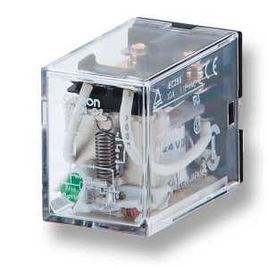
Dimension and Shapes
The different kinds of relays come in different shapes and dimensions. The dimension of the relay varies from manufacturer to manufacturer. The datasheet of each relay is available to study its dimensions. The general dimension of the relays is about 43 * 10 * 25 mm. The shapes of the relays also vary from manufacturer to manufacturer. The common shapes of the relays are rectangular. The selection of the relay dimension and the shape is based on the choice of the user according to the circuit or the panel where the relay is being used.
Relay Products
-
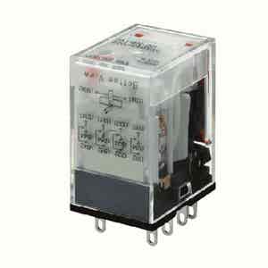
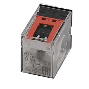
 In StockMY4-GS-R DC24 BY OMZ - MY4-GS-R DC24
Omron
SKU: OM_MY4-5704D
Model: MY4-GS-R DC24 BY OMZ
SGD $8.61 All prices inclusive of GST -
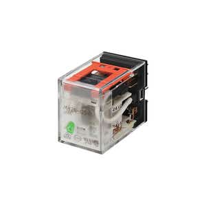
 In StockMY2N-GS-R DC24 BY OMZ - GENERAL PURPOSE RELAYS
Omron
SKU: OM_MY2-5709H
Model: MY2N-GS-R DC24 BY OMZ
SGD $10.41 All prices inclusive of GST -
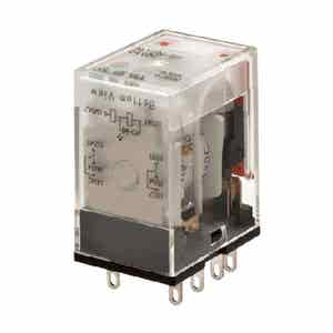
 In StockMY4N-GS-R AC220/240 - GENERAL PURPOSE RELAYS
Omron
SKU: OM_MY4-5708G
Model: MY4N-GS-R AC220/240
SGD $12.64 All prices inclusive of GST - In StockMY2-GS-R AC220/240
Omron
SKU: OM_MY2-5703R
Model: MY2-GS-R AC220/240
SGD $7.06 All prices inclusive of GST - In StockMY4-GS-R AC220/240 - GENERAL PURPOSE RELAYS
Omron
SKU: OM_MY4-5703F
Model: MY4-GS-R AC220/240
SGD $8.31 All prices inclusive of GST - In StockMY2-GS-R AC24 BY OMZ - MY2-GS-R AC24
Omron
SKU: OM_MY2-5700D
Model: MY2-GS-R AC24 BY OMZ
SGD $7.06 All prices inclusive of GST -
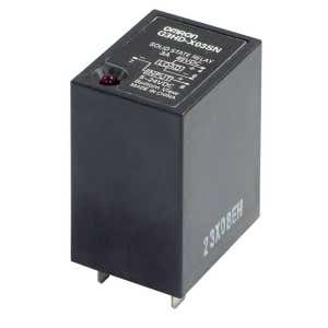
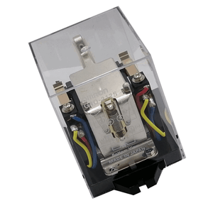 In StockG4Q-212S AC220 - Ratchet Relay
Omron
SKU: OM_G4Q-1172B
Model: G4Q-212S AC220
SGD $93.40 All prices inclusive of GST -
 In StockLY2N DC24 BY OMI - GENERAL PURPOSE RELAYS
Omron
SKU: OM_LY2-5161M
Model: LY2N DC24 BY OMI
SGD $10.90 All prices inclusive of GST -
 In StockMY2N-GS AC24 BY OMZ - GENERAL PURPOSE RELAYS
Omron
SKU: OM_MY2-5505B
Model: MY2N-GS AC24 BY OMZ
SGD $10.41 All prices inclusive of GST -
 In StockMY4N-GS-R DC24 BY OMZ - GENERAL PURPOSE RELAYS
Omron
SKU: OM_MY4-5709E
Model: MY4N-GS-R DC24 BY OMZ
SGD $12.64 All prices inclusive of GST -
 In StockG2R-1-SND DC24(S) BY OMB - GENERAL PURPOSE RELAYS
Omron
SKU: OM_G2RN8794M
Model: G2R-1-SND DC24(S) BY OMB
SGD $15.12 All prices inclusive of GST -
 In StockMY4N-GS DC24 BY OMZ - MY4N-GS DC24 Relay and PYFZ-14-E Socket (Set)
Omron
SKU: OM_MY4-5509B
Model: MY4N-GS DC24 BY OMZ
SGD $6.65 All prices inclusive of GST -
 In StockMY2N-GS-R AC220/240 - GENERAL PURPOSE RELAYS
Omron
SKU: OM_MY2-5708M
Model: MY2N-GS-R AC220/240
SGD $10.41 All prices inclusive of GST - In StockMY2-GS-R DC24 BY OMZ - MY2-GS-R DC24
Omron
SKU: OM_MY2-5704G
Model: MY2-GS-R DC24 BY OMZ
SGD $7.06 All prices inclusive of GST -
 In StockMY4-GS AC100/110 BY OMZ - GENERAL PURPOSE RELAYS
Omron
SKU: OM_MY4-5501G
Model: MY4-GS AC100/110 BY OMZ
SGD $9.67 All prices inclusive of GST -
 In StockG2RV-ST500 24VDC
Omron
SKU: OM_G2RV8208E
Model: G2RV-ST500 24VDC
SGD $23.44 All prices inclusive of GST -
 In StockMY4N AC200/220 - GENERAL PURPOSE RELAYS (IA)
Omron
SKU: OM_MY4-1236R
Model: MY4N AC200/220
SGD $24.78 All prices inclusive of GST -
 In StockG2R-2-SND DC24(S) BY OMB - GENERAL PURPOSE RELAYS
Omron
SKU: OM_G2RN8833D
Model: G2R-2-SND DC24(S) BY OMB
SGD $15.74 All prices inclusive of GST - In StockMY2-GS DC24 BY OMZ - GENERAL PURPOSE RELAYS
Omron
SKU: OM_MY2-5504D
Model: MY2-GS DC24 BY OMZ
SGD $9.05 All prices inclusive of GST - In StockLY2N AC220/240 BY OMI - GENERAL PURPOSE RELAYS
Omron
SKU: OM_LY2-5158M
Model: LY2N AC220/240 BY OMI
SGD $10.90 All prices inclusive of GST
-
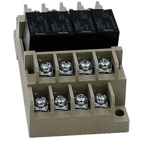
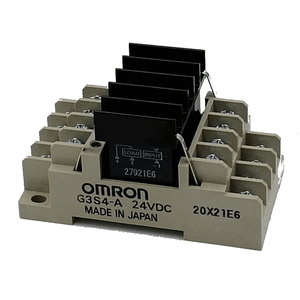 In StockG3S4-A DC24 - TERMINAL RELAY
Omron
SKU: OM_G3S41013R
Model: G3S4-A DC24
SGD $165.61 All prices inclusive of GST -
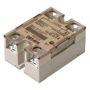 In StockG3NA-220B-UTU DC5-24 BY OMZ - Solid State Relays
Omron
SKU: OM_G3NA7022H
Model: G3NA-220B-UTU DC5-24 BY OMZ
SGD $64.42 All prices inclusive of GST -
 In StockG3SD-Z01P-PD-US DC24 - Solid State Relays
Omron
SKU: OM_G3SD1023F
Model: G3SD-Z01P-PD-US DC24
SGD $18.96 All prices inclusive of GST -
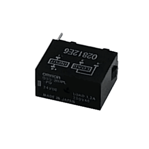 In StockG3S-201PL-PD DC24 - Solid State Relays
Omron
SKU: OM_G3S-1023H
Model: G3S-201PL-PD DC24
SGD $28.49 All prices inclusive of GST -
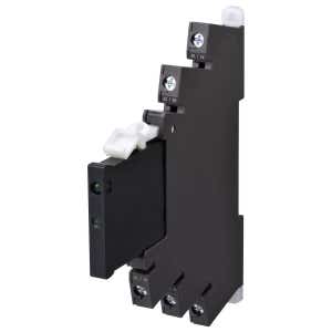 In StockG3RV-SR700-D AC/DC24 - Slim Solid State Relays
Omron
SKU: OM_G3RV5030M
Model: G3RV-SR700-D AC/DC24
SGD $110.36 All prices inclusive of GST -
 In StockG3H-203SN-VD DC5-24 - Solid State Relays
Omron
SKU: OM_G3H-1045M
Model: G3H-203SN-VD DC5-24
SGD $54.13 All prices inclusive of GST - In StockG3NA-210B-UTU DC5-24 BY OMZ - Solid State Relays
Omron
SKU: OM_G3NA7019H
Model: G3NA-210B-UTU DC5-24 BY OMZ
SGD $48.68 All prices inclusive of GST -
 In StockG3S4-D DC24 - TERMINAL RELAY
Omron
SKU: OM_G3S41015E
Model: G3S4-D DC24
SGD $136.50 All prices inclusive of GST -
 In StockG3S4-D1 DC24 - TERMINAL RELAY
Omron
SKU: OM_G3S41016C
Model: G3S4-D1 DC24
SGD $117.80 All prices inclusive of GST -
 In StockG3FD-X03SN-VD DC5-24 - Solid State Relays
Omron
SKU: OM_G3FD1015M
Model: G3FD-X03SN-VD DC5-24
SGD $47.57 All prices inclusive of GST -
 In StockG3S4-D DC12 - TERMINAL RELAY (Clearance Sale)
Omron
SKU: OM_G3S41008B
Model: G3S4-D DC12
SGD $6.17 All prices inclusive of GST -
 In StockG3PJ-225B-PU DC12-24 - Solid State Relays
Omron
SKU: OM_G3PJ2102M
Model: G3PJ-225B-PU DC12-24
SGD $135.02 All prices inclusive of GST -
 In StockG3PE-245B-2N DC12-24 - Solid State Relays
Omron
SKU: OM_G3PE2036F
Model: G3PE-245B-2N DC12-24
SGD $503.14 All prices inclusive of GST -
 In StockG3PJ-215B DC12-24 - Solid State Relays
Omron
SKU: OM_G3PJ2001E
Model: G3PJ-215B DC12-24
SGD $76.80 All prices inclusive of GST -
 In StockG3PE-235B DC12-24 - Solid State Relays (IA)
Omron
SKU: OM_G3PE2003M
Model: G3PE-235B DC12-24
SGD $141.70 All prices inclusive of GST -
 In StockG3S4-D1 DC5 - TERMINAL RELAY
Omron
SKU: OM_G3S41010D
Model: G3S4-D1 DC5
SGD $115.69 All prices inclusive of GST - In StockG3NA-D210B-UTU DC5-24 BY OMZ - Solid State Relays
Omron
SKU: OM_G3NA7126G
Model: G3NA-D210B-UTU DC5-24 BY OMZ
SGD $98.35 All prices inclusive of GST -
 G3PE-225B 12-24VDC Solid State Relays
Omron
SKU: OM_G3PE4002B
Model: G3PE-225B 12-24VDC
SGD $89.92 All prices inclusive of GST -
 G3PW-A260EU-S - Single phase power controller, standard type, 60 A, screw terminals
Omron
SKU: OM_G3PW1005E
Model: G3PW-A260EU-S
SGD $972.65 All prices inclusive of GST - G3PW-A260EC-C-FLK - Single phase power controller, constant current type, 60 A, SLC terminals
Omron
SKU: OM_G3PW1008M
Model: G3PW-A260EC-C-FLK
SGD $1,164.61 All prices inclusive of GST

Share this article on social media